Memory interfacing in 8085 microprocessor pdf serial#
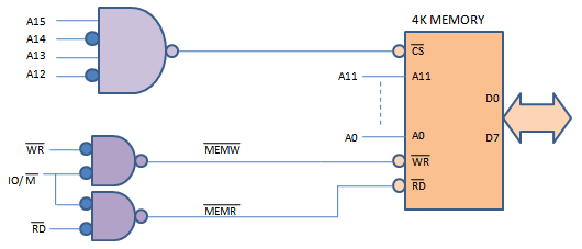
Peripheral/Externally Initiated Operations Reset Interrupt Ready Hold Īrchitecture of 8085 Power Supply – a +5V DC power supply Maximum clock frequency of 3MHz 8-bit general purpose microprocessor 16-bit Address Bus Capable of addressing 64K of memory Īrchitecture 0f 8085 Cont… ALU Timing and Control Unit General Purpose Registers Program Status word Program Counter Stack Pointer Instruction Register and Decoder Interrupt Control Serial I/O Control Address Bus Data Bus Īrchitecture 0f 8085 Cont… Arithmetic Logic Unit (ALU) 8085 has 8-bit ALU Performs arithmetic & Logic operations on data Timing & Control Unit Generates timing and control signals General Purpose Registers 8-bit registers (B,C,D,E,H,L) 16-bit register pairs (BC, DE, HL,PSW) Īrchitecture 0f 8085 Cont… Program Status Word (PSW) Accumulator and Flag Register can be combined as a register pair called PSW Instruction Register and Decoder Instruction fetched from memory is stored in Instruction register (8-bit register) Decoder decodes the instruction and directs the Timing & Control Unit accordingly Īrchitecture 0f 8085 Cont… Interrupt Control 8085 has 5 interrupt signals INTR – general purpose interrupt RST 5.5 Restart Interrupts RST 6.5 RST 7.5 TRAP – non-maskable interrupt The interrupts listed above are in increasing order of priority Īrchitecture 0f 8085 Cont… Serial I/O Control 8085 has two signals for serial communication SID – Serial Input Data SOD – Serial Output Data Īrchitecture 0f 8085 Cont… Address Bus Used to address memory & I/O devices 8085 has a 16-bit address bus Lower-order Address Higher-order Address Data Bus Used to transfer instructions and data 8085 has a 8-bit data bus Data Bus A 15 A 14 A 13 A 12 A 11 A 10 A 9 A 8 AD 7 AD 6 AD 5 AD 4 AD 3 AD 2 AD 1 AD 0Ĩ085 Communication with Memory Involves the following three steps Identify the memory location (with address) Generate Timing & Control signals Data transfer takes place ĭemultiplexing Address/Data Bus 8085 identifies a memory location with its 16 address lines, (AD0 to AD7) & (A8 to A15) 8085 performs data transfer using its data lines, AD0 to AD7 Lower order address bus & Data bus are multiplexed on same lines i.e. Internal Operations Store 8-bit data Perform Arithmetic and Logic Operations Test for conditions Sequence the execution of instructions Store/Retrieve data from stack during execution

Microprocessor Initiated Operations Memory Read Memory Write I/O Read I/O Write Logic Pinout of 8085 Data Bus Address Bus Control & Status Control & Status Externally initiated signals Serial I/O ports Power Supply & frequencyĨ085 Operations Microprocessor Initiated Operations Internal Operations Peripheral/Externally Initiated Operations

Pinout Diagram of 8085 A 40-pin IC Six groups of signals Address Bus Data Bus Control and Status pins Power Supply & frequency signals Externally initiated Signals Serial I/O ports

8085 Microprocessor: Architecture & Support ComponentsĬontents Pin diagram of 8085 8085 Operations Architecture of 8085 8085 Communication with Memory


 0 kommentar(er)
